V.st
v.st boards
 This is the high-speed DAC that is used to generate the analog voltages for vector displays. In the current form it has four analog outputs, X/Y/Z/W, with 12-bits each and a swing from -12 to +12 volts for X/Y and 0-5 volts for Z and W. There are trim pots to adjust the scale on the X and Y axes independently. It works with displays like the Vectrex game console, the Tek 1720 vectorscope, or oscilloscopes with XY mode. The software interface reads lists of XY points from the serial port and uses DMA to generate the vectors with no hot-spots. Patches to MAME allow retro-gaming of Atari (and other) vector games.
Wiring
 These are the instructions for wiring the 2015-11-02 version of the board used in the vector display class. The six pin header that spans SV1 and SV2 has the analog signals. They are (from left to right in the above image):
| Pin | Function |
|---|---|
| 1 | NC (was 2.5V reference in original design, no longer used) |
| 2 | X+, goes from 0-5V, or -2.5 to +2.5V relative to X- |
| 3 | Y+, goes from 0-5V, or -2.5 to +2.5V relative to Y- |
| 4 | Ground (connect if your signal has an actual ground pin) |
| 5 | Z+ (brightness, if your display supports it) |
| 6 | X-, Y- and Z-. Reference 2.5V from the fourth DAC channel. |
Protocol
This protocol design is a work in progress. Comments are appreciated! source code for the firmware is at github.com/osresearch/vst.
The first goal for the protocol is to have it be very low overhead and also self-synchronizing. Since MAME or Processing can exit mid-write, it is important that the Teensy be able to recover and re-sync with the frame.
Vectors are 3 bytes, sent MSB first. X and Y are 11-bits (0 to 2047), brightness is two bits (1=transit, 2=normal or 3=bright). Brightness 0 indicates the end of the list of vectors and that the Teensy should start drawing them.
unsigned out = 0
        | (brightness & 0x3) << 22
        | (x & 0x3FF) << 11
        | (y & 0x3FF) << 0
        ;
uint8_t cmd[] = {
        out >> 16,
        out >>  8,
        out >>  0,
};
Since brightness == 0 means that there are no more vectors, three or more zero bytes in a row indicate that the frame is done. Four zeros in a row would never occur in a valid vector list, so to force a resync with the teensy you can send a long string of zeros as part of the initialization.
There are several possible extensions on the protocol:
- Font drawing.
- Circle segment.
- Parameter setting (flip, rotate, draw speed, transit speed, etc).
- Compressed relative points: if the dx and dy are less than (signed) 6 bits, perhaps we can use one of the brightness bits to indicate that this is a continuation and save a byte on the transfer.
- Front end vector sorting to reduce transit time.
BOM
 The design for the v.st quad analog vector board (available from oshpark) has the following components:
- MAX6105 - 5V reference
- MAX6102 - 2.5V reference
- MCP4922 - 12bit SPI DAC
- TL3474 - 4 MHz general purpose opamp (x2)
- RB-0512D - +12V and -12V DC-DC converter
BNC edge launch (x2)- 75 Ohm and 10K resistors (1%)
- TC33X trimpot (20K, allows gain up to 2X)
- Misc caps
- Headers
- Teensy 3.1
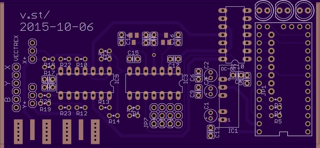 Known board issues in 2015-10-06 board (fixed in 2015-11-02 version):
DAC X output and reference voltage are swappedOpamp circuit needs to be reworked into a differential amplifier to swing -5 to +5Brightness should have a separate DAC, rather than just an amp.Brightness does not have 75 Ohm resistorAnalog ground plane should cover top of board as well- DACs are limited to 20-25 MHz bit clock. Could do high-speed current output.
- ???
Known software issues:
- Bresenham is too slow, leading to hotspots when the DMA at 25 MHz gets ahead of the software. Can it be optimized? YES.
- Occasionally the protocol gets confused. it should be self synchronizing, so figure out why.
- Circle segments? Should we do this?
- Should we add fonts (or a font)?
- Better overlap of serial reads and vector generation. Should be able to do both simultaneously.
- Tuning constants without recompilation: need flip, rotate, brightness shift, etc in EEPROM. Command protocol updates to adjust and tune.
- Real-time clock crystal? This would make for easy scope-clock applications.