PDP 11
PDP-11/34
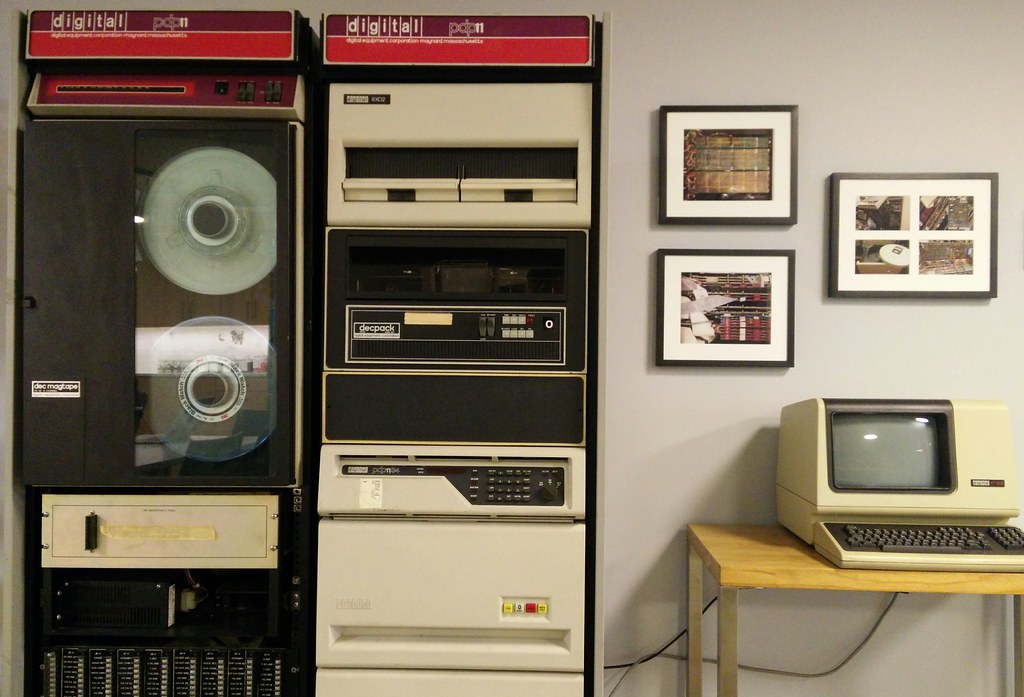 We rescued two PDP-11/34 computers and their associated equipment from a storage unit in the Bronx and have been working on getting one of them running again. It is now on static display at my office.
 |
 |
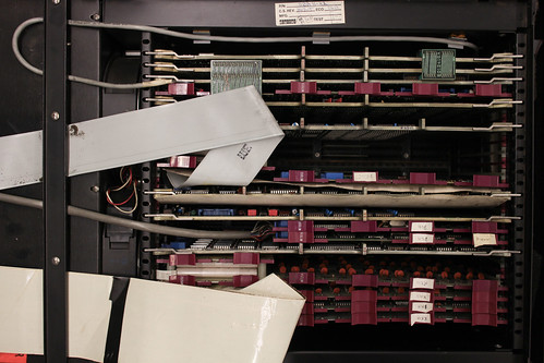
The PDP-11 uses a wire-wrapped Unibus backplane with many cards. The top four are the CPU, the next is 64 KB of memory, then a few "bus grant cards", the console controller, some others, and finally the disk controller. See "Options" below for more details.
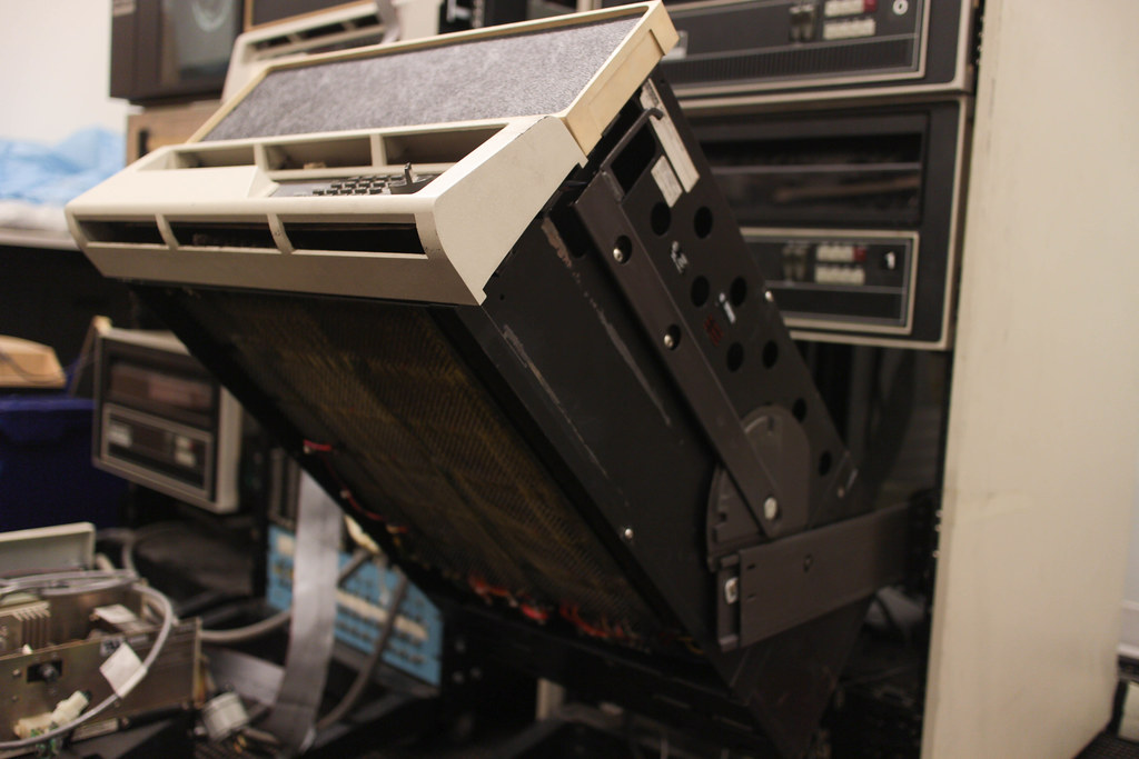 Adding or removing cards requires adjusting the wirewrap on the bottom of the backplane, so there rack slides are built to allow the CPU chassis to be positioned at 45 or 90 degrees for easy access.
Options

Option  Module  Purpose
CPU M8266   11/34A control module (Replaces M7266)
CPU M8265   11/34A data paths module (Replaces M7265)
        M8267   11/34A floating point processor
        M9312   Bootstrap terminator with 5 empty ROM sockets; one for CPU diagnostics, 4 for peripheral boots
KY11-LB M7859   Console interface; programmer's console (11/34a)
MS11-JP M7847-DJ    16-Kword 18-bit RAM
MS11-JP M7847-DJ    16-Kword 18-bit RAM
MS11-JP M7847-DJ    16-Kword 18-bit RAM
MM11-BP/CP  M7850   Parity board for G651, MS11-EP/FP/HP/JP
        G727    Grant continuity card with DMA link (NPR), single
        M9202   UNIBUS connector, inverted (M9192+M9292 assembled 1" apart with 2' cable)
        G727    Grant continuity card with DMA link (NPR), single
        M9202   UNIBUS connector, inverted (M9192+M9292 assembled 1" apart with 2' cable)
        G727    Grant continuity card with DMA link (NPR), single
MM11-BP/CP  M7850   Parity board for G651, MS11-EP/FP/HP/JP
DR11-C  M7860   M786+M105+M7821; general device interface to PDP11
MS11-JP     16-Kword 18-bit RAM
MS11-LB
MS11-LB M7891-BB    64-Kword 18-bit parity MOS memory
DL11    M7800   Async transmitter & receiver, 110-2400 baud, no clock (Replaces KL11, which consisted of M780, M105, M782)
DL11-W  M7856   RS-232 SLU & realtime clock option
DZ11-A  M7819   8-line double-buffered async EIA with modem control (50 to 96-Kbaud, 64-byte silo)
        M9202   UNIBUS connector, inverted (M9192+M9292 assembled 1" apart with 2' cable)
        G727    Grant continuity card with DMA link (NPR), single
        M9202   UNIBUS connector, inverted (M9192+M9292 assembled 1" apart with 2' cable)
RK11-D  M7254   RK05 status control module
RK11-D  M7255   RK05 disk control module
            DR bus cable
RK11-D  M7256   RK05 registers module (data path)
RK11-D  M7257   RK05 bus control module
??  ??  ??
Booting
I have written a longer boot strap walkthrough.
Bootstrap toggle switches
 |
 |
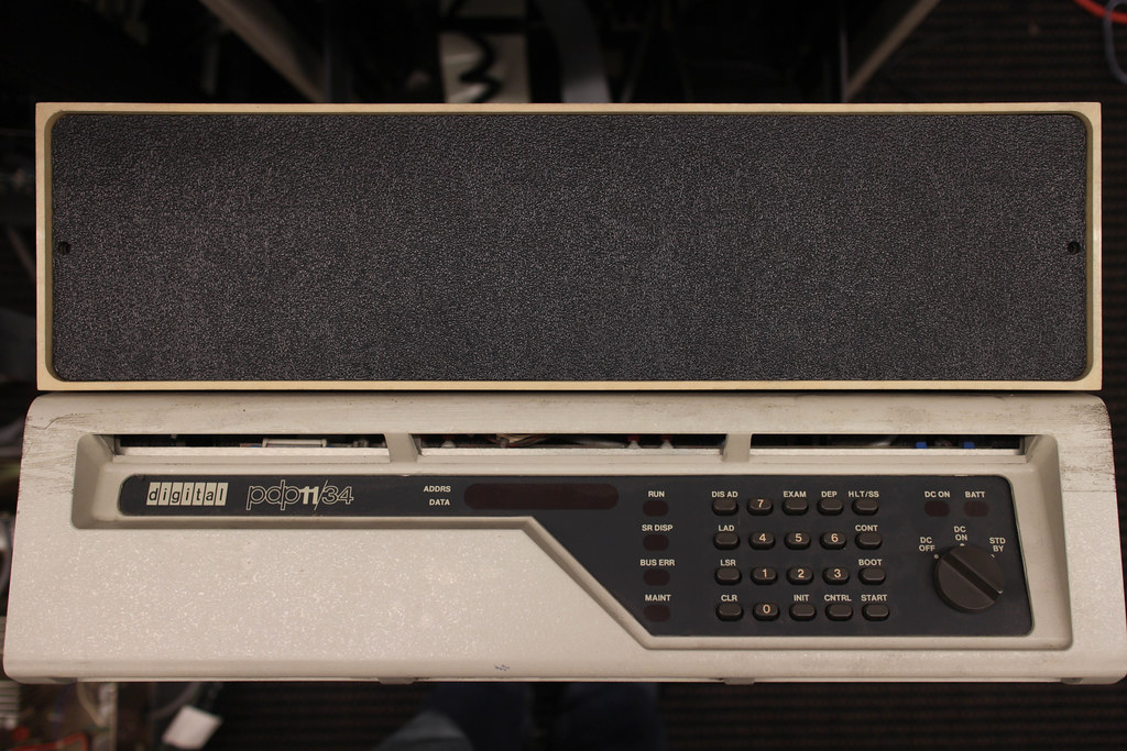
The boot sequence had to be toggled in on the earlier models, but the /34 has an octal keypad so you can type the addresses and values rather than flipping binary switches. The sticker on one of the PDP-11/34 units has the startup code for booting from the RK05 drive; we've typed it in and single stepped through the instructions to verify that the CPU functions:
LA  010000
DEP 012737
        000005
        177404
        000777
LA  010000
Start
Wait 1 sec
LA  000000
Start
. p4
This is similar to the Bootstrap RK02/03/05 Disk Unit x sample code:
        Loc.    Cont.   Instruction Comment
        =======================================
        001000  012737  mov #unit,rkda  set the unit address
        001002  000000          unit 0
            020000          unit 1
            040000          unit 2
            060000          unit 3
        001004  177412
        001006  012700  mov #rkwc, r0   controller address
        001010  177406
        001012  012710  mov #-256,(r0)  set the word count
        001014  177400
        001016  012740  mov #5,-(r0)    read command
        001020  000005
        001022  105710  tstb (r0)   wait for ready
        001024  100376  bpl .-2
        001026  000000  halt        (or 005007 to auto start)
Boot ROM card
 However, this machine has a M9312 "bootstrap / Unibus terminator" board, which has a several small bootroms for different devices like the RK05 decpack drive, RL02 harddrive or TU11 tape drive and also includes a serial console interface. This card allows the the machine to be booted with push button convenience using the VT100 terminals that we've restored.
-
Make sure the PDP-11 power switch is in the "DC off" position
-
Power on the VT100, make sure it is configured for 9600/9600 (or whatever your console card DIP switches are set to)
-
Power on the drives using the large switch on the PDU
-
Open the RK05 #0 drive and install the
pizzaDECpack -
Toggle the switch from "LOAD" to "RUN"
-
Turn on the PDP-11 by switching to "DC on"; the big fans should start.
-
Hit Control+Boot on the front panel. The terminal should display the four registers (in octal) and an
@prompt:
000000 1734000 165212 165212
@
- Type in "
DK" to boot from the DK boot rom, which should load RT-11 or whatever OS you have installed on the RK05 decpack. In the case of RT-11, it will also execute the commands inSTARTS.COMfile. One of ours prints on startup:
RT-11SJ (S)V03B-005
.SET TT: QUIET
.INS MX
?KMON-F-No handler file on SY:

.

- The
.is the prompt for the user. Try "DIR" or "HELP". - To mount the second disk, run:
ASSIGN RK1 B:
SHOW
DIR B:
If you want to try running a simulated PDP-11, you can use simh to emulate it with these old operating systems.
Media
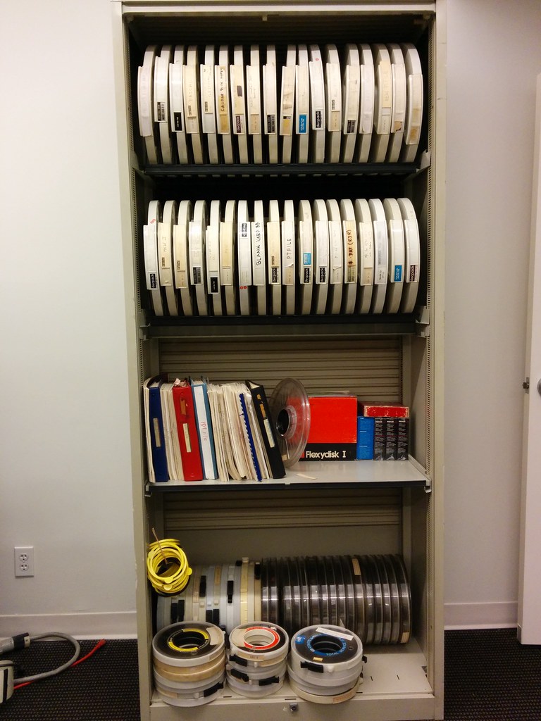 Also included racks of tapes, drive platers, floppies, etc. We haven't begun to sort through it all yet. One of the tapes does promise "digitized monkey brain", so I can't wait to get the tape drive working.
RK05
 |
 |
One of the RK05 drives had been powered down with a decpack platter still installed. We had to remove the cover to retract the heads and actuate the front door release. The head assembly includes this charming vernier scale.
We tried dumping the various platters from the system using the RT-11 COPY command:
COPY/NOQUERY/DEVICE RK0: TT:
and saving the output from a USB serial port adapter. This transfers fairly close to the 9600 baud "line rate" at 870 bytes/sec. Although this seems to not output NUL characters, so the files are not usable. Oh well. As quick hack, DUMP can be used instead:
DUMP/IGNORE/WORDS/NOASCII/TERMINAL RK0:
This unfortunately sends 7 characters for every two byte word, as well as some additional overhead that means it is almost 4x as slow as the binary output.
RL01
 Both of the RL01 drives are in good shape and functional. One of them even has
 BASIC.SAV, so we can relive our youth. Due to the size of the drives (ten megabytes) we haven't tried to dump them yet.
Terminals
 |
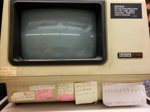 |
There were a dozen various VT100 terminals of various vintages, although we haven't found many that work. Most of them seem to have bad CRT tubes, although the control board are functional. This one has an embedded CPU, possibly a PDP-11/110 of its own or a Z80.