TRS80 Model 100 + Raspberry Pi
 Thirty years ago in 1983 the first tablet computer was released: the Tandy / RadioShack TRS-80 Model 100. It ran for weeks on four AA batteries and gathered quite a following. Despite the 1099 (1399 with extra 8-KB of memory) introductory price tag, features like the built in 300 baud modem with acoustic couplers made them very popular with reporters in the field, and the built-in BASIC programming language (written by Bill Gates himself!) made them easy to adapt into various custom applications. Over six million were produced and as a result, inexpensive, used Model 100s are readily available now. Amazingly many of them still work perfectly and there is a somewhat active Club100 fan club.
 I bought one that was non-functional for $20 with the goal of replacing the 80C85 motherboard with a more modern AVR or ARM CPU. While this particular motherboard had failed sometime ago due to bad capacitors, the LCD and keyboard were in perfect working order. Thanks to the combination of the age of the design, the system's low original clock speed (2.4 MHz) and its 5 V logic make it simple for modern hardware to drive. Moore's Law also means that the entire motherboard can be shrunk into a PCB with almost zero chips other than the MCU. Read on for what is involved in building a new brain for your Model 100.
LCD Module
 The 240x64 LCD module has a 5x2 array of ten Hitachi HD44102 display drivers, each of which drive a 50x32 rectangle on the module (the last two only have 40 columns connected). These are pure bitmap displays -- there is no character generator hardware. Intriguingly, the designers cut out square holes in the circuit board and mounted half of the chips inverted "dead bug" style inside of the board. This simplified the circuit layout, as you can see from the parallel traces between the pairs of chips.
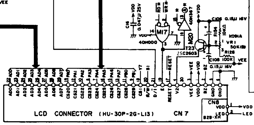
The 30-pin header provides ten individual chip select lines, one for each driver, and an 8-bit wide data bus plus a variety of other control lines. I could drive the chip select with a decade counter, but that would require additional components and complicate the circuit board. Instead I use the entire PORTF and a few additional pins to interface with it.
 The breadboard required 15 traces to be cut so that I could solder the 30 pin connector to it, and since the connector is now partially covering the topside of the board, there are wires on the bottom as well. White are data lines, brown are chip select and green are other signaling.
 The additional complication is that these older LCDs require significant negative bias voltage on the
 VEE pin to display an image. Since I wanted to run it off of USB or AAA batteries, I used a two diode, two capacitor charge pump and one of the many PWM outputs to generate the negative voltage. The analog contrast voltage on the V2 pin had been adjusted with a potentiometer in the original design; I'm using a second PWM output via a low-pass filter capacitor to generate it via software instead.
At boot time the software runs the lcd_init() function to configure all of the pins, configure the PWM outputs, and then send commands to each of the ten drivers to bring them up in 8-bit mode, page 0. They come up with random garbage, so it is important to clear the contents before proceding.
Fonts
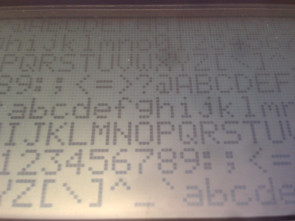 Since the LCD does not have a character generator, we have to generate our own fonts. The display is 240x64 and the normal "small" font is a 5x7 with a 6x8 bounding box. This gives us the traditional 40x8 resolution. My font is stored in program memory in
 font.c, one byte per column. Underline and reverse video flags are supported, although scrolling has not yet been implemented.
Another reason for using an 8 pixel vertical bounding box is the efficiency of writing to the LCD. The display drivers accept an 8 pixel tall write command, aligned on an 8 pixel boundary. If the vertical portion of the font spans this boundary we need to either keep a 16 KB frame buffer to redraw the additional portions (hard to do with only 4 KB of SRAM), or spend extra time to read/modify/write the pixels from the display drivers. This might be implemented in a later version of my code.
Line drawing using Bresenham's algorithm is possible, but will require RMW as well. I haven't implemented it yet, but it was present in the Microsoft BASIC on the original device.
Keyboard
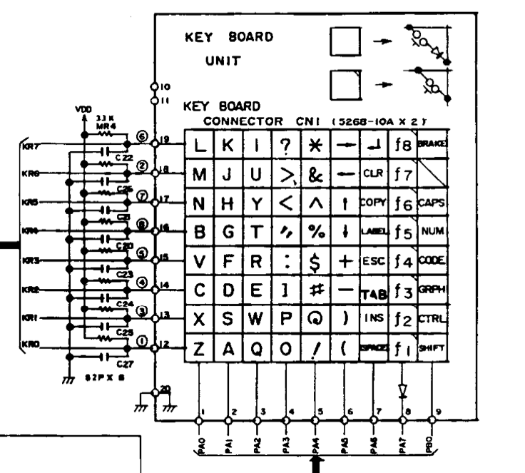
The keyboard is a normal matrix design, with marvelous mechanical keyswitches instead of rubber dome membranes, and with the Control key in the right place. It's not quite a nice as a Model M buckling spring, but still very comfortable for extended typing. The downside is that it lacks several modern common programming characters, such as ~, |, { and }. Trigraphs are one option, as are using the CODE modifier key to select them. Other oddities are that Capslock and Numlock are a mechanically locking keys, and the Left and right shift do not have separate scancodes
 My original design shared the data port between the LCD and the keyboard rows, but this lead to garbage on the screen depending on which keys were held down while the LCD commands were being written. My new design uses dedicates
 PORTA to the keyboard rows, while it continues to share the 9 column lines with the LCD. The source in keyboard.c has been updated.
To read the keyboard, keyboard_init() drives all of the columns high and activates pull ups on all of the rows. The scan routine then drives one column line low and reads all of the rows to see if any of them are being driven low against the pullup resistors. Currently only one key is returned at a time and there is no software debouncing -- the original design debounced in hardware on the mainboard. Both of these could be future improvements.
VT100 emulation
 I've implemented enough of the VT100 command set in
 vt100.c to allow vi and lynx to run. The escape code parser is not even close to compliant and could stand for a rigorous state machine implementation. There are lots of documents online that list various subsets of the codes; I used umich's vt100.codes.txt. See it in action.
Future work?
 My initial version was on a breadboard and now it is on a more permanent protoboard, but designing a proper PCB would be a good step. Something that can mount inside the original case using existing mounting holes and run off batteries would be ideal.
 Currently the only function I have implemented in the firmware is a USB serial terminal. The real Model 100 had a text editor and a programming language, in addition to a (non-VT100) serial monitor and an analog modem. Porting busybox vi to the AVR is doable now that there is a VT100 emulator, and using something like pForth for the interactive programming wouldn't take much code space.
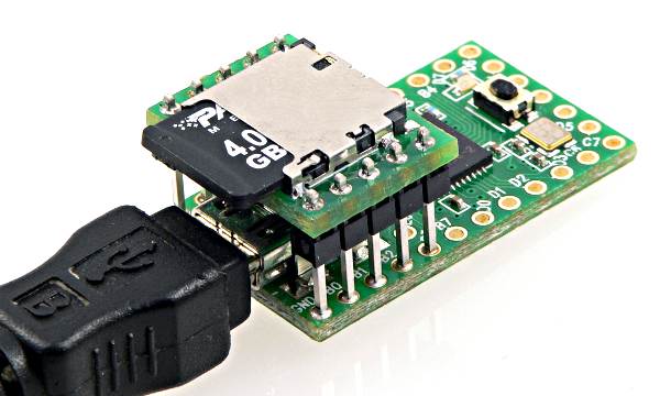
Adding MicroSD card support to store documents would expand the space available from the original 32 KB to 32 GB, a minor factor of one million. Plus the SD cards are non-volatile, so all of your work wouldn't be lost when the batteries die. Another option would be to add a Raspberry Pi (or maybe Bunnie's awesome homemade laptop) into the case, using the Teensy to act as a serial console for it since the Pi lacks sufficient IO and 5V tolerance.
If you're interested in upgrading your Model 100, here is my source code and schematics for the board. Perhaps these devices will have another thirty years of life left in them with a few minor upgrades...
 The acoustic coupler works on the original Model 100. It would be fun to build a software 300 baud FSK modem that can drive it, but where would you find a phone to use it with? They don't quite fit modern phones and VoIP seems to mess up the signaling.
Originally posted to the NYCR blog
Retrocomputing Raspberry Pi Teensy 2013