Signed multiplication with FPGA DSP blocks

The Lattice iCE40 FPGA
has a 16x16 DSP block that can replace a "soft" multiplier and adder
with far less logic and with a much higher fMAX. It produces a 32 bit output in a
single cycle, although as of 2021 yosys and nextpnr won't infer a DSP based multiplier,
so it is necessary to explicitly use the SB_MAC16 block.
For softcore 32-bit CPUs like Claire Wolf's picrorv32 that have a 64-bit (optionally signed) multiply instruction, it is possible to chain four of the iCE40's DSP blocks to produce a 32x32-bit to 64-bit multiplier and still meet the 25 MHz timing requirement.
DSP Overview

The DSP function usage for iCE40 devices
app note from Lattice shows the many subcomponents inside the SB_MAC16 primitive.
Externally it has four 16-bit inputs named A, B, C, and D, as well as carry-in and -out
bits, and a 32-bit output named O.
Internally it has a 16x16 mutiplier built from two 8x8 multipliers connected to A and B, and two 16x16 adders
that can be connected to the outputs of the multipliers as well as C and D, and all of this
is configured with numerous control bits.
The mode that we're using as a building block implements a 16x16 multiplier with a 32-bit accumulator, with a 33-bit output (32-bits plus a carry). The Verilator version shows the equivilant operation that the configuration bits select:
module mult16x16(
        input clk,
        input [15:0] a,
        input [15:0] b,
        input [31:0] c,
        output [32:0] prod
);
`ifdef VERILATOR
        wire [32:0] ab = a * b;
        assign prod = ab + c;
`else
        SB_MAC16 #(
                .TOPOUTPUT_SELECT(2'b00), // adder, unregistered
                .TOPADDSUB_LOWERINPUT(2'b10), // multiplier hi bits
                .TOPADDSUB_UPPERINPUT(1'b1), // input C
                .TOPADDSUB_CARRYSELECT(2'b11), // top carry in is bottom carry out
                .BOTOUTPUT_SELECT(2'b00), // adder, unregistered
                .BOTADDSUB_LOWERINPUT(2'b10), // multiplier lo bits
                .BOTADDSUB_UPPERINPUT(1'b1), // input D
                .BOTADDSUB_CARRYSELECT(2'b00) // bottom carry in constant 0
        ) mult16x16_add(
                .CLK(clk),
                .A(a),
                .B(b),
                .C(c[31:16]),
                .D(c[15:0]),
                .O(prod[31:0]),
                .CO(prod[32])
        );
`endif
endmodule
While a clk input is supplied, it is unused in this design and there are no flipflops
or registers in this module. The prod and implicit carry outputs are continuous assignment,
so they will update continuously as the a, b, and c inputs change. It is possible
to configure internal flipflops in the SB_MAC16 block, but they are not used.
Unsigned multiply
Baseline multiplier
module mult32x32unsigned_baseline(
        input clk,
        input [31:0] a,
        input [31:0] b,
        output [63:0] prod
);
        assign prod = a * b;
endmodule
As a base line, the "fast multiplier" in the picorv32 does an explicit multiply and allows yosys to synthesize the 32x32-bit to 64-bit output, which uses nearly 2700 logic cells of the 5000 in the up5k.
First try
32x32-bit unsigned multiply is "easy" to derive by re-writing the expression.
For instance, if we want to compute the 32-bit multiply of two unsigned
values 0x12345678 and 0x9ABCDEF0, we can split them into four
16-bit values, where << is a shift by that many bits:
0x12345678 = 0x1234 << 16 + 0x5678 << 0
0x90ABCDEF = 0x90AB << 16 + 0xCDEF << 0
The product can then be expanded into four multiplies and some number of additions:
0x12345678 * 0x90ABCDEF
  = (0x1234 << 16 + 0x5678 << 0) * (0x90AB << 16 + 0xCDEF << 0)
  = (0x1234 * 0x90AB) << 32
  + (0x1234 * 0xCDEF) << 16
  + (0x5678 * 0x90AB) << 16
  + (0x5678 * 0xCDEF) << 0
  = 0x0A4968BC << 32
  +     0x0EA4A28C << 16
  +     0x30DD4228 << 16
  +         0x458ED208 << 0
This could be implemented in Verilog exactly like this with the mult16x16() module:
module mult32x32unsigned_noaccumulate(
    input clk,
    input [31:0] a,
    input [31:0] b,
    output [63:0] prod
);
    wire [15:0] al = a[15:0];
    wire [15:0] ah = a[31:16];
    wire [15:0] bl = b[15:0];
    wire [15:0] bh = b[31:16];

    wire [32:0] al_bl;
    wire [32:0] ah_bl;
    wire [32:0] al_bh;
    wire [32:0] ah_bh;

    mult16x16 al_bl_mult(clk, al, bl, 0, al_bl);
    mult16x16 ah_bl_mult(clk, ah, bl, 0, ah_bl);
    mult16x16 al_bh_mult(clk, al, bh, 0, al_bh);
    mult16x16 ah_bh_mult(clk, ah, bh, 0, ah_bh);

    assign prod = ah_bh[31:0] << 32
        + (al_bh[31:0] + bh_al[31:0]) << 16
        + al_bl[31:0] << 0;
endmodule
Although the need for a 64-bit ripple adder across the four partial products is a significant slow down on the fMAX for the design. It is, however, a significant improvement over the base line: only 680 logic cells are required.
Using the accumulator
We can do better, however, since the DSP also includes a 32-bit accumulate
input and can implement a "fused multiply accumulate" (FMAC) operation.
The lower 16-bits of al_bl go directly to the output, while the upper 16-bits
can be fed in as the accumulator input to ah_bl, and the full 32-bit output
of ah_bl can be fed into al_bh. Likewise the lower 16-bits of al_bh go
directly to the output, while the upper 16-bits can be fed into the accumulator
input for ah_bh.
The only difficulty is now we must think about where carry-out is possible
so that we can ensure that is correctly propagated. It is usually easiest to
think about what happens when both A and B are 0xFFFFFFFF.
For al*bl, even if they are both 0xFFFF the result 0xFFFE0001 is still less
than the 32-bit output, so it can't carry.
The ah*bl + al*bl[31:16] is 0xFFFE0001 + 0xFFFE = 0xFFFEFFFF, so it can't
carry either.
But al*bh + (ah*bl + al*bl[31:16]) is 0xFFFE0001 + 0xFFFEFFFF = 0x1FFFD0000,
so it is possible that there is a carry output and 17-bits need to be propagated
to the ah*bh computation.
module mult32x32unsigned(
        input clk,
        input [31:0] a,
        input [31:0] b,
        output [63:0] prod
);
        wire [15:0] al = a[15:0];
        wire [15:0] ah = a[31:16];
        wire [15:0] bl = b[15:0];
        wire [15:0] bh = b[31:16];

        wire [32:0] al_bl;
        wire [32:0] ah_bl;
        wire [32:0] al_bh;
        wire [32:0] ah_bh;

        mult16x16 al_bl_mult(clk, al, bl, 0, al_bl);
        mult16x16 ah_bl_mult(clk, ah, bl, { 16'h0000, al_bl[31:16] }, ah_bl);
        mult16x16 al_bh_mult(clk, al, bh, ah_bl[31:0], al_bh);
        mult16x16 ah_bh_mult(clk, ah, bh, { 15'h0000, al_bh[32:16] }, ah_bh);

        assign prod[63:32] = ah_bh[31:0];
        assign prod[31:16] = al_bh[15:0];
        assign prod[15:0] = al_bl[15:0];
endmodule
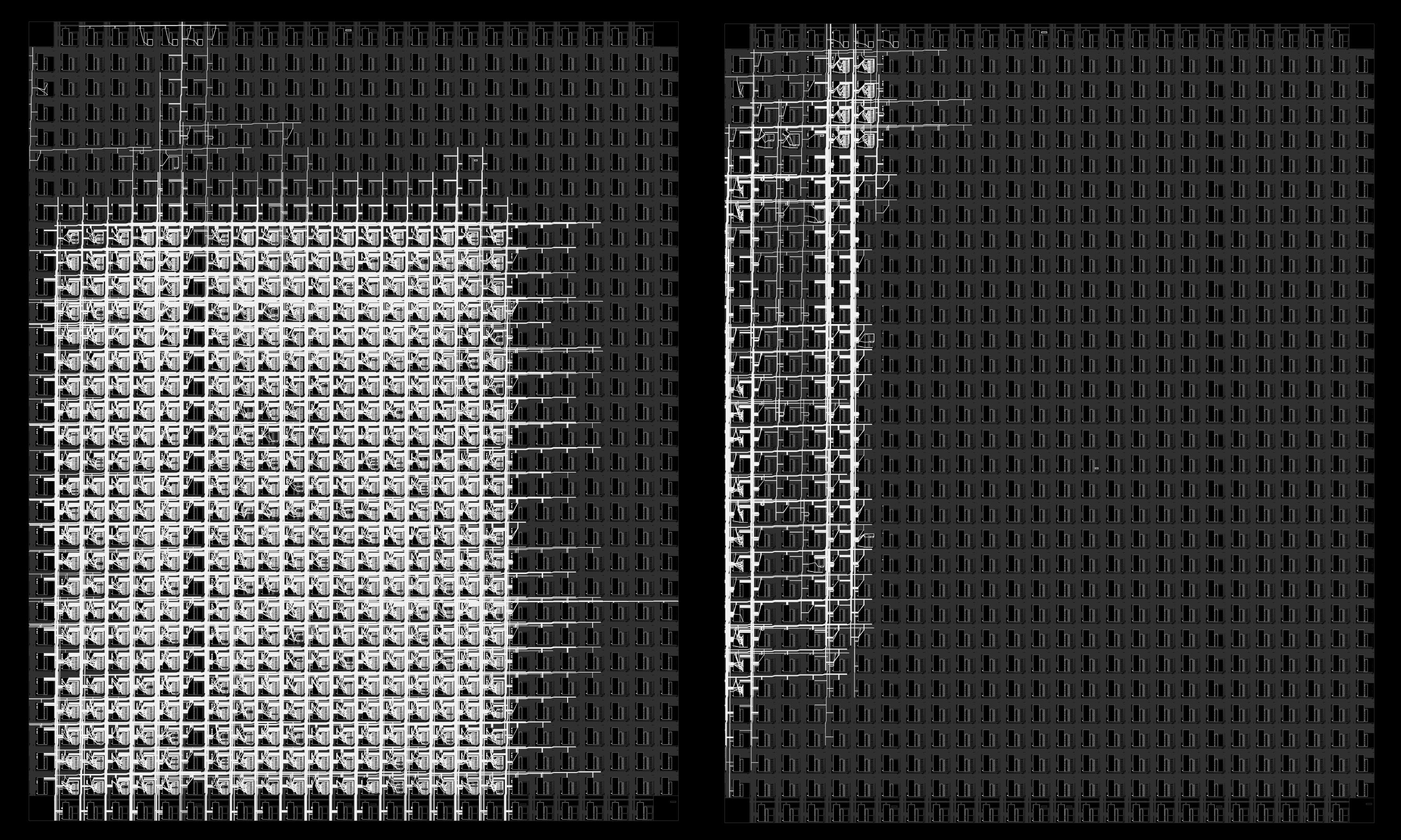
This version uses only 68 logic cells in the iCE40, a 98% reduction! In the nextpnr-ice40 --gui
output the amount of die area used by the Verilog multiplier (on the left) compared to the
DSP multiplier (on the right) is really striking. Additionally if the 32-bit counters
for a and b are replaced with something faster, the fMAX of the DSP system is 127 MHz
compared to 20 MHz for the Verilog multiplier.
Signed multiply
Signed multiplication is similiar, except that there is an implicit "sign extension"
on the leading bit if the operand is signed. In the above example, if both of the
values are signed, 0x12345678 (00010010001101000101011001111000 in binary) is positive
since the leading bit is zero, while 0x90ABCDEF (10010000101010111100110111101111 in binary)
is negative since the leading bit is 1. This means that the 64-bit multiplication is actually
0x0000000012345678 times 0xFFFFFFFF90ABCDEF when the leading bits are "extended" to the full size.
In the signed multiplier we can ignore this since 0 times anything is still zero.
This means that the 64-bit result can be expanded into the 16-bit chunks (and ignoring ones where the resulting output is either trivially zero or shifted beyond 64-bits):
0x0000000012345678 * 0xFFFFFFFF90ABCDEF
= (0x00000000 << 32 + 0x1234 << 16 + 0x5678 << 0)
* (0xFFFFFFFF << 32 + 0x90AB << 16 + 0xCDEF << 0)
  = (0xFFFFFFFF * 0x12345678) << 32
  + (0x1234 * 0x90AB) << 32
  + (0x1234 * 0xCDEF) << 16
  + (0x5678 * 0x90AB) << 16
  + (0x5678 * 0xCDEF) << 0
  =
         | 64| 48| 32| 16| 0 |
  + 0x12345677EDCBA988 << 32
  +         0x0A4968BC << 32
  +             0x0EA4A28C << 16
  +             0x30DD4228 << 16
  +                 0x458ED208 << 0
The bottom 32-bits are unaffected by this sign extension, so they can be
computed as before, and anything over the 64-bit length can be ignored.
The other thing to note is that multiplying by 0xFFFFFFFF is the same as negating
the value, so this can be re-written as:
  + 0x0A4968BC << 32
  +     0x0EA4A28C << 16
  +     0x30DD4228 << 16
  +         0x458ED208 << 0
  - 0x12345678 << 32
Todo: figure out how to use the DSP to handle this sign extension and carry.