Motorola MDT9100 conversion

Several Motorola MDT-9100T "Mobile Data Terminals" came up on eBay and their retro-future design was too neat to pass up. The stylish housing combined with an aperture-less amber CRT looks like something slipped from the Fallout or BladeRunner universe into our own. Some of us at NYC Resistor bought them and are repurposing them.
Windows 3.1
 The original system had an i386SX running Windows 3.1 in a locked-down kiosk mode that would only allow the radio application to run. phooky figured out how to get a DOS prompt and used the installed LapLink tool to transfer some 1990s demo scene programs to his. I wanted to make mine into a more modern computer, while preserving the amber CRT and keyboard.
 |
 |
The BIOS setup screen can be reached with the "HOME" key during the boot and is a nostalgia trip. "Boot Sector Virus Protection" is such a throw back. There is also a debug mode to get a command prompt by hitting Left-Shift + Alt during the mirror_c Scanning message (which might not be visible since the CRT takes some time to warm up).
Among the funny bits of trivia about the MDT-9100:
Although Motorola advertised the MDT-9100 as suitable for secure data communication, the standard version was in fact highly insecure ... According to Motorola, a 'special code' was used, but the code appeared to be nothing more than plain ASCII. The data protcol was known as the MDT-4800 protocol and used bit-interleaving as a means to correct transmission errors, and to obscure the data stream. When hackers discovered the properties of the protocol, several PC programs appeared that allowed the general public to monitor police conversations with nothing more than a scanner, a PC and a simple interface
Powering the MDT9100
 There is a +12V connector on the bottom and the system draws about 1.7 amps when it is running. The shielded one on the terminal is ground, the unshielded is positive (this cable end would have the opposite, preventing accidental shorts to ground if the connector was unplugged). There is also a 12V connector on the back, but it is only for the radio and can be left disconnected. I think this two pole towing connector is the right one; I carefully used aligator clips.
BeagleBone Black setup

In order to replace the i386 with a BeagleBone Black it was necessary to build an adapter board that plugs into the ribbon cable, deduce the VGA timings and write a Device Tree overlay (DTBO) to configure the LVDS framing for the special screen, and design a USB HID keyboard interface for the keyboard and function keys.
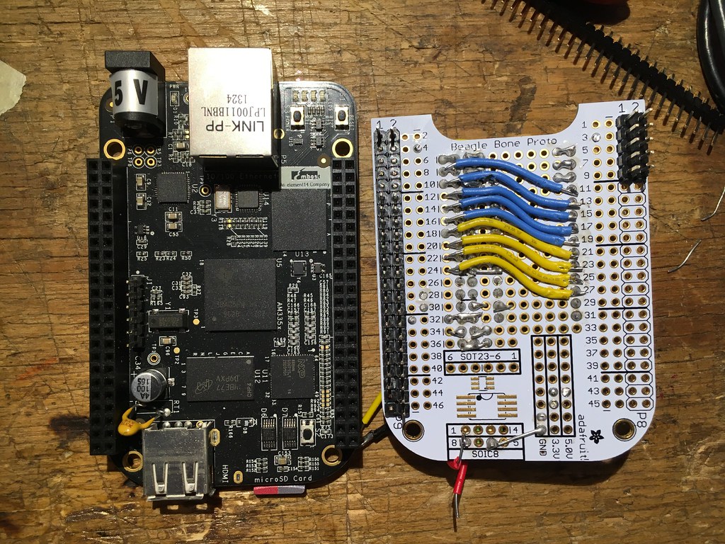 My first version is built on a BBB Prototyping Cape board. I had the bright idea of using it upside down so that the Teensy and 0.1" headers were better aligned, but this was a mistake -- there are many pins that are not mirrored on the proto cape and this resulted in having to cut away quite a few of the header pins to avoid boot mode problems or worse.
This is a good candidate for a real PCB with a proper DAC for the video. Maybe later...
Ribbon cable
 The i386 connects to the keyboard and CRT through a 0.1" 16x2 header. The +12V power and ground are doubled up on the right hand side.
| Function | Function | ||
|---|---|---|---|
| Keyboard | GND | Caps lock LED | |
| Keyboard | Col 9 | Col 8 | |
| Keyboard | Col 7 | Col 6 | |
| Keyboard | Col 5 | Col 4 | |
| Keyboard | Col 3 | Col 2 | |
| Keyboard | Col 1 | Col 0 | |
| Keyboard | Row 0 | Row 1 | |
| Keyboard | Row 2 | Row 3 | CRT |
| Keyboard | Row 4 | Row 5 | CRT |
| Keyboard | Row 6 | Row 7 | CRT |
| Fn Col 10 | Fn Col | CRT | |
| Fn Col 12 | CRT status LED (2.2K) | CRT | |
| Monitor enable | Send Lamp? | CRT | |
| +12V | +12V | CRT | |
| !Hsync | !Vsync | CRT | |
| GND | GND | CRT |
BeagleBone LVDS setup
 |
 |
The video is 0-1 V analog on the coax cable and I probed the ribbon cables with the oscilloscope. the horizontal sync pulses are active-low, 31.4KHz and the vertical sync pulses are also active-low for two frames and every 60Hz. This directly matches VGA 640x480@60Hz (confirmed by tinyvga) with a 25.175 MHz dot clock.
 |
 |
Based on my previous success with using the BeagleBone Black to drive a MacSE monochrome CRT, I thought I could use the LVDS framing hardware to do the same for the MDT9100. This required revisiting the Device Tree hackery and dealing with the lack of documentation plus the unhelpful error messages from loading the DTB files. Here's the key part of the display-timings section of the MDT9100-TILCDC-00A0.dts file:
       display-timings {
            native-mode = <&timing0>;
            timing0: 640x480@60 {
                        hactive = <640>;
                        vactive = <480>;
                        hback-porch = <48>; // in pixels
                        hfront-porch = <16>; // in pixels
                        hsync-len = <96>; // in pixels
                        vback-porch = <33>; // in pixels
                        vfront-porch = <10>; // in pixels
                        vsync-len = <2>; // in lines
                        clock-frequency = <25200000>; // should be 25175000
                        hsync-active = <0x0>; // active low
                        vsync-active = <0x0>; // active low
                        linux,phandle = <0x4>;
                        phandle = <0x4>;
                };
        };
There is something wrong with the clock-frequency field -- if it is set to the exact value for VGA the hardware outputs at 1Hz rather than 60Hz. No clue why that is happening, but the 25.2MHz is close enough for the non-multisync CRT.
 |
 |
Using a 5-bit R2R resistor ladder (similar to my first Vector display), the top bits of the green channel of the LCD output (LCD6-LCD10) can be merged into an analog value for feeding into the CRT. This works, although it isn't the most linear. Using the LCD15 pins were problematic -- there seems to be a problem with the BBB's boot mode pins that would cause a hang if the R2R ladder was installed at boot time. The green channel doesn't seem to have this problem.
 One of the units had a bad flyback transformer and finding a replacement transformer has been unsuccessful so far, so it might be replaced with an actual LCD. Until then this one has provided additional parts to the other units.
Keyboard interface

The qwerty section is on the left half of the ribbon cable, the function keys are on the CRT section. The function keys have not yet been mapped. Probing the twenty pins going to the qwerty section revealed a 10 column by 8 row matrix, with diodes on each key. Oddly the anodes of each diode connect to the rows, which requires pull-down resistors in the interface.. Pin 19 is the Caps Lock LED and pin 20 is the ground for the LED (but is otherwise unused).
The matrix layout is:
| 0 | 1 | 2 | 3 | 4 | 5 | 6 | 7 |
|---|---|---|---|---|---|---|---|
| Row 0 | 1 | 2 | 3 | 4 | 5 | 6 | 7 |
| Col 0 | Esc | Home | Numlock | PrtScr | ScrLck | Pause | Insert |
| 1 | ? | ? | ? | ? | ? | ? | ? |
| 2 | Main | 1 | 2 | 3 | 4 | 5 | 6 |
| 3 | 8 | 9 | 0 | - | = | Backspace | Page Up |
| 4 | Q | W | E | R | T | Y | U |
| 5 | O | P | [ | ] | Page Down | CapsLock | A |
| 6 | D | F | G | H | J | K | L |
| 7 | " | Left Shift | Z | X | C | V | B |
| 8 | M | , | . | / | Right Shift | Up | End |
| 9 | Alt | SPACE | ~ | \ | Left | Down | Right |
| 10 | ? | ? | ? | ? | F11 | F8 | F5 |
| 11 | ? | ? | ? | F1 | F12 | F9 | F6 |
| 12 | ? | ? | ? | F2 | Send | F10 | F7 |
Six of the rows are shared with the function key section and @phooky mapped the additional five pins going to the CRT section (columns 10-12, the large emergency lamp, a smaller RED LED).
There is a row/matrix keyboard driver built with a Teensy 3.2 in the mdtkey.ino file that makes the keyboard and function keypad appear as if it is a normal USB HID keyboard.
Applications
 Everyone compares it to the Fallout Pipboy, so I added a video playback of the Fallout 4 second screen app. The PypBoy 3000 software also runs on the BBB with the installation of the PyGame and a few other packages.
 Running Doom is the modern definition of Turing equivalence and the prdoom packages install on the BBB with no problems.
 If anyone has any Robocop "Omni Consumer Products" themed applications, let me know!
Radios

I haven't had time to hack on the radios at all. I'm assume they are serial connected of some sort, although even with my amateur-extra rating I'm not sure I can use them. If anyone wants to try them out, get in touch with me!
More info

-
github.com/osresearch/mdt9100- Source for the beaglebone black DTS and Teensy keyboard interface - phooky's album, with many good photos of the i386 board
- CryptoMuseum article on the MDT-9100
- Hackaday "From cop data terminal to retro computer"