Homebrew interface for the HTC v1 Lighthouses
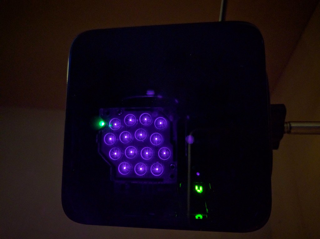
HTC Vive Lighthouse

The HTC Vive uses a really innovative way to add 3D pose estimation and position sensing to their VR experience. The "Lighthouse" design works like classic naval lighthouses, updated to work in 3D at 60Hz 30Hz and using IR instead of visible light. Gizmodo tears one down to show how the internals work. In keeping with Alan Yates' statement that "The 1st rule of Lighthouse is make interoperating implementations", I've built an Arduino / ESP8266 Teensy 3 library to make it easy to add indoor position sensing to smaller projects.
Sensor selection
The easy way

The easiest way to receive the lighthouse laser sweep data is with the Triad Semiconductor TS3633-CM1 sensor module. This single unit replaces an entire breadboard of passives and transistors, and outputs an easy to process waveform. The 10-pack for $7/sensor is not too expensive. It is 3.3V, so be sure to wire it from the regulated output of the Teensy, not the unregulated VBus input. Do note that the STANDBY pin must be wired low for it to function. I've heard that the next version of the module will remove this requirement.
The castelated sensor is breadboardable on standard 0.1" headers and I've found that it is easiest to setup a jig with headers on the both sides to keep it level while soldering the four necessary pins. All of my math and configurations assume that the sensors are in a 22mm square, which is 10 squares on the breadboard.
The decoder on the Teensy 3 requires both edge triggers; I haven't figured out how to make InputCapture.cpp do the right thing with a single channel, so instead I've wired each sensor to two input captures and use one for rising and one for falling. This means that four sensors, rather than eight, can be handled by a single Teensy. That's enough for prototyping.
The hard way
 |
 |
The sweep pulses are quite short, so fast photosensors are necessary. I've been experimenting with the VEMT4700 850nm transistors (120 degree FOV) and can receive the signal up to about 1m away. This isn't sufficient for playing, but good enough for further testing. The problem is that the phototransistor is not fast enough to detect the few ns pulse of the sweeping laser when further away. Alan Yates posted this tweet showing an opamp circuit to decode the Lighthouse beacon using the BPW34 photodiode.
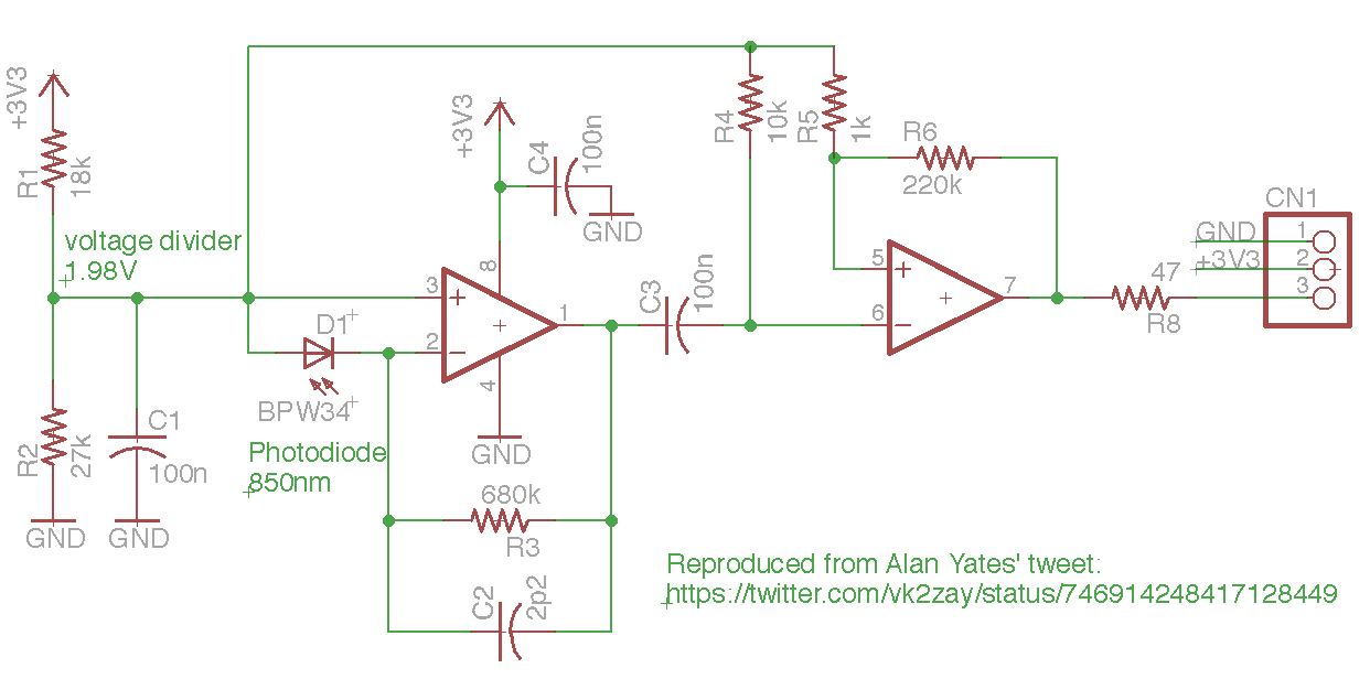
The opamps in the schematic are slow, but provide better amplification than the direct phototransistor. There is lots of noise if the sensor is exposed to light and I found that it worked much better with an IR filter (built from an old floppy disk).
 |
 |
I built something like this circuit with 10 MHz opamps and the BPW34 sensors. It seems to work up to several meters, unlike the phototransistor .

Alan also posted a discrete transistor amplifier version that is much faster. it decodes the signal quite well, but is a pain to build due to the number of passive components. A PCB layout is needed to make this usable, especially for a multi-photosensor project.

The Teensy 3 firmware uses the input capture functions of the Flexible Timer to record the time of the falling edges on the output of the comparators into hardware registers synced with the 48 MHz PLL. This offloads all of the CPU and provides accurate timing independent of CPU load. Unfortunately two of the opamp circuits seem to be misbehaving, so it is hard to get a calibration measurement. Analog circuits are hard.
Timing data
The two Lighthouses must be in visual range of each other and coordinate so that they pulse together and sweep their lasers separately (sort of like TDMA). The sync pulses are long, around 100 microseconds and fire at 120 Hz for each lighthouse. The sweeps from the lasers depend on how close the sensor is to the lighthouse and seem to range from 0 to 20 microseconds.
Position calculation

There are two steps involved in computing position and orientation with the Lighthouse sensors. The first is a one-time calibration to compute the position and orientation of the Lighthouses, which establishes the XYZ origin and set of basis vectors for the real-world space. This is not currently implemented in the Teensy since it uses an offline numeric solver to approximate the best solution for an over-determined system -- the computed position and orientation matrices for each Lighthouse are stored in the Teensy and then used for the realtime, 30 Hz position updates.
Calibration

The computation of the Lighthouse positions requires four sensors in a known rigid configuration and a numerical solver. There might be a closed form solution, although since it only needs to be done during setup or configuration, the slowness of the solver is ok. The code for this is in solve-lighthouse.
Begining with the assumption that the Lighthouse is at coordinates (0,0,0) in its own reference frame, we're able to compute the unit ray vectors for each of the sensors from the angle measurements. The four positions in the lighthouse frame are at unknown offsets from the center of the lighthouse:
We can know the distances between each of the sensor positions since they are in a rigid configuration and can write six equations in terms of those known/measured values:
\begin{align} r_{01} & = |\vec{p}_0 - \vec{p}_1| & r_{02} & = |\vec{p}_0 - \vec{p}_2| & r_{03} & = |\vec{p}_0 - \vec{p}_3| \\ r_{12} & = |\vec{p}_1 - \vec{p}_2| & r_{13} & = |\vec{p}_1 - \vec{p}_3| & r_{23} & = |\vec{p}_2 - \vec{p}_3| \end{align}
Looking at just the first one we can rearrange it to make it amenable to solving, remembering that \hat{v}_0, \hat{v}_1 are unit vectors and that \hat{v}_0 \cdot \hat{v}_1 is the cosine of the angle between the two vectors.
\begin{align} r^2_{01} & = |\vec{p}_0 - \vec{p}_1|^2 \\ & = |k_0\hat{v}_0 - k_1\hat{v}_1|^2 \\ & = (k_0 v_{0x} - k_1 v_{1x})^2 + (k_0 v_{0y} - k_1 v_{1y})^2 + (k_0 v_{0z} - k_1 v_{1z})^2 \\ & = k^2_0 v^2_{0x} - 2k_0k_1 v_{0x}v_{1x} + k^2_1 v^2_{1x} \\ & + k^2_0 v^2_{0y} - 2k_0k_1 v_{0y}v_{1y} + k^2_1 v^2_{1y} \\ & + k^2_0 v^2_{0z} - 2k_0k_1 v_{0z}v_{1z} + k^2_1 v^2_{1z} \\ & = k^2_0 (v^2_{0x} + v^2_{0y} + v^2_{0z}) + k^2_1 (v^2_{1x} + v^2_{1y} + v^2_{1z}) - 2 k_0 k_1 (v_{0x} v_{1x} + v_{0y} v_{1y} + v_{0z} v_{1z}) \\ & = k^2_0 |\hat{v}_0|^2 + k^2_1 |\hat{v}_1|^2 - 2 k_0 k_1 (\hat{v}_0\cdot\hat{v}_1) \\ & = k^2_0 + k^2_1 - 2 k_0 k_1 (\hat{v}_{0}\cdot\hat{v}_{1}) \end{align}
This allows us to write a six equation system to find the four unknowns (k_0, k_1, k_2, k_3) and pass it into the Python numeric solver:
\begin{align} 0 & = k^2_0 + k^2_1 - 2 k_0 k_1 (\hat{v}_{0}\cdot\hat{v}_{1}) - r^2_{01} \\ 0 & = k^2_0 + k^2_2 - 2 k_0 k_2 (\hat{v}_{0}\cdot\hat{v}_{2}) - r^2_{02} \\ 0 & = k^2_0 + k^2_3 - 2 k_0 k_3 (\hat{v}_{0}\cdot\hat{v}_{3}) - r^2_{03} \\ 0 & = k^2_1 + k^2_2 - 2 k_1 k_2 (\hat{v}_{1}\cdot\hat{v}_{2}) - r^2_{12} \\ 0 & = k^2_1 + k^2_3 - 2 k_1 k_3 (\hat{v}_{1}\cdot\hat{v}_{3}) - r^2_{13} \\ 0 & = k^2_2 + k^2_3 - 2 k_2 k_3 (\hat{v}_{2}\cdot\hat{v}_{3}) - r^2_{23} \\ \end{align}
        sol = nsolve((
            k0**2 + k1**2 - 2*k0*k1*v01 - r01**2,
            k0**2 + k2**2 - 2*k0*k2*v02 - r02**2,
            k0**2 + k3**2 - 2*k0*k3*v03 - r03**2,
            k2**2 + k1**2 - 2*k2*k1*v12 - r12**2,
            k3**2 + k1**2 - 2*k3*k1*v13 - r13**2,
            k2**2 + k3**2 - 2*k2*k3*v23 - r23**2,
        ),
            (k0, k1, k2, k3),
            (1000,1000,1000,1000),
            verify=False  # ignore tolerance of solution
        )
With a well averaged set of sensor readings (currently 200) the estimated error in the distance from the lighthouse to the sensors is less than 1mm, although occasionally it is around 10mm (due to nearly colinear rays?). I also don't have a good error estimate for the orientation accuracy.
Given the distances k_0,k_1,k_2,k_3 from the lighthouse to the sensors computed above, the position of the lighthouse \vec P in the sensor reference frame can be computed by another numeric solve that tries to find the single point that is the correct distance from each of the sensors:
\begin{align} k^2_0 & = |\vec P - \vec p_0|^2 \\ k^2_1 & = |\vec P - \vec p_1|^2 \\ k^2_2 & = |\vec P - \vec p_2|^2 \\ k^2_3 & = |\vec P - \vec p_3|^2 \\ \end{align}
When the estimates of the sensor distances is less than 1mm, this computed position seems to be very accurate, but at 10mm error the position is many meters away from where it should be. Perhaps the solution is to suggest a small rotation in the sensor to the user if the estimated error is so far out of range.
The next step is to compute the transformation matrix from the lighthouse rotated reference frame to the new origin. This math needs to be worked out.
Sync pulse decode
To be written: Code is in LighthouseSensor.cpp. Pulse length information from nairoi/LighthouseRedox/Light_Emissions.md.
Todo: decode the OOTX data.
Calculation

Given a lighthouse configuration (x,y,z,\phi,\theta,\psi) for the two lighthouses, we can compute the position of a single sensor plus an error estimate with the four angular measurements from the two sensors. The code is in LighthouseXYZ.cpp.
Handwaving, the idea is to compute the two unit ray vectors for sensor n from the Lighthouses k 0 and 1 based on the angle measurements and rotate by the Lighthouse k's rotation matrix M_k:
\hat{v}_{nk} = M_k \begin{bmatrix} 0 \\ \cos(\theta_{nk}) \\ \sin(\theta_{nk}) \\ \end{bmatrix} \times \begin{bmatrix} \cos(\phi_{nk}) \\ 0 \\ -\sin(\phi_{nk}) \\ \end{bmatrix}
The sensor's two rays \hat{v}_{n0}, \hat{v}_{n1}, originating at P_{0}, P_{1} are then intersected by finding the distance between the lines.
\begin{align} L_{n0} & = P_{0} + s_0 \hat{v}_{n0} \\ L_{n1} & = P_{1} + s_1 \hat{v}_{n1} \\ \end{align}
We want to find the two unknowns s_0, s_1 such that the distance |L_{n1} - L_{n0}| is minimized, assuming that \hat{v}_{n0}, \hat{v}_{n1} are not parallel. If the lines intersect, this is easy to compute, but if there is any error the line segment between the two points will be perpendicular to both rays. If this line segment is w_c = L_{n1} - L_{n0}, we know that:
0 = \hat{v}_{n0} \cdot \vec{w}_c =\hat{v}_{n1} \cdot \vec{w}_c
External links
- crashspace - position aware device: Matt Pinner uses this code to create real-world LED art
- LighthouseRedox/docs/Light Emissions.md -- more details on pulses and details
- BPW34 photodiode -- recommended sensor?
- Alan Yates hadware comments
- Teensy PulsePosition -- sampling via polling is much too inaccurate, so the FTM hardware must be used instead. This allows roughly 20ns accuracy.
- National Semiconductor Photodiode tutorial