Ikea
 Ikea Tradfri LED power supplies with wireless receiver are cheap and easily modifiable. Some of them have accessible SWD programming headers allowing openocd to debug and modify the firmware.
Overview
 This is a an expanded verison of a short talk that I gave at ThingsCon 2019 on installing MicroPython onto Ikea's HomeSmart devices. I like to take things apart, and recently I've been disassembling Ikea Tradfri/HomeSmart devices to see what is inside of them.
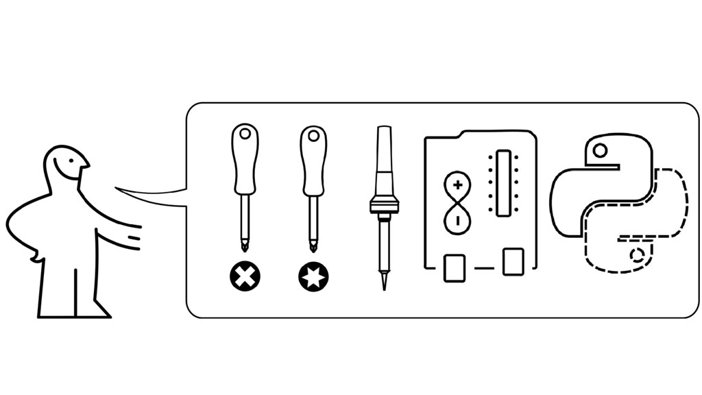 In order to do so, you will need a cross-head screw driver, a Torx driver, a soldering iron, an Arduino or Teensy, and some MicroPython experience.
 These modifications will void your warranty, so don't contact Ikea if you're confused about these steps. If it breaks, you get to keep both pieces.
 Using the Torx driver, remove the four screws by turning them in a counter-clockwise direction.
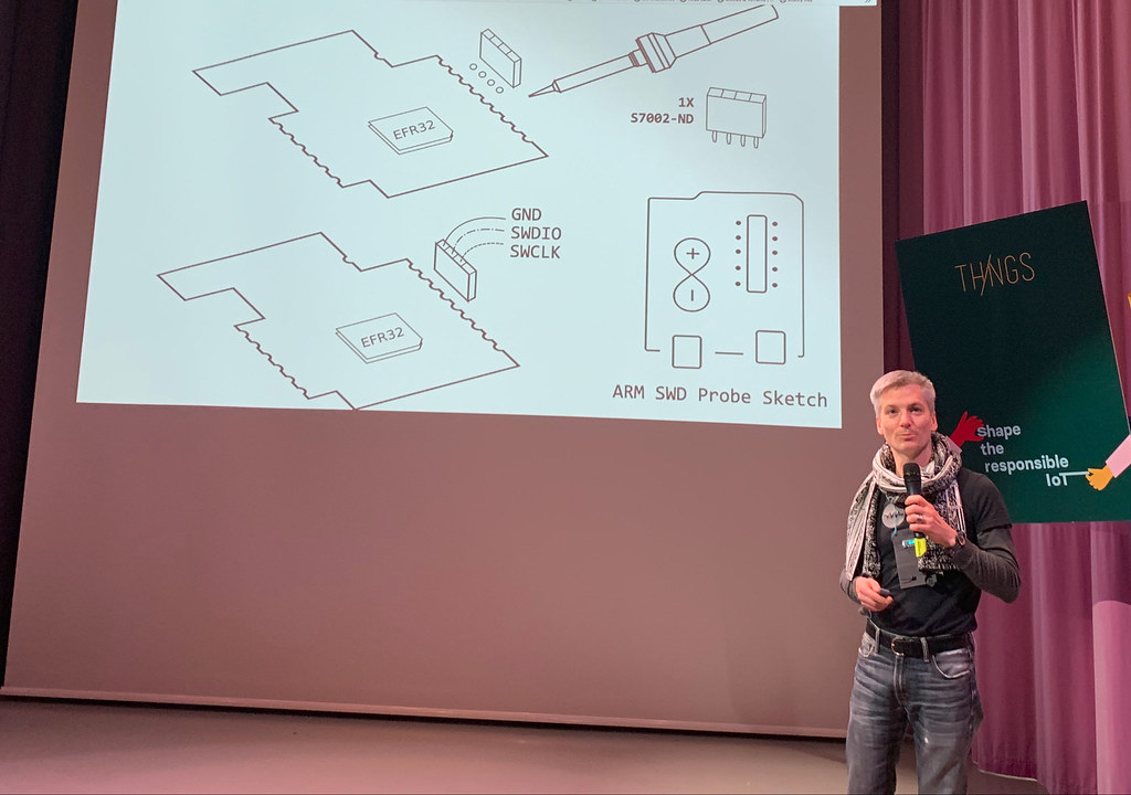
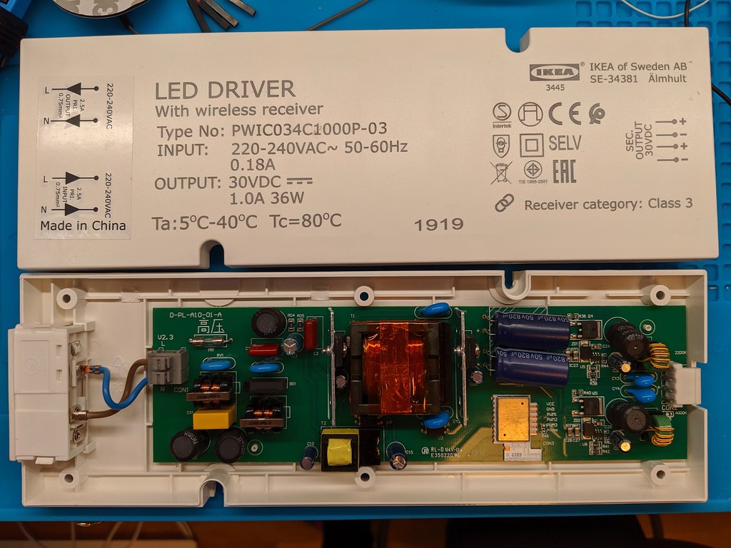
 Removing the case will reveal the 220V AC power input, the 24V AC-DC converter, a Silicon Labs EFR32 board with low-side PWM driver, and a set of parallel LED outputs. Be careful not to touch the live AC input while the system is plugged in.
 The CPU board is a Silcon Labs EFR32 "Wireless Gecko", which has a reasonable 256 KiB of program flash, 32 KiB of SRAM, a very nice 16-bit PWM for smooth dimming, and a ZigBee radio.
 Ikea also thoughtfully wired the debug port on the 10W LED driver, although the FLOALT requires soldering directly to the board. Using your soldering iron, solder a four pin female header to the port. Then connect the Ground,
 SWDIO and SWDCLK pins to the Arduino or Teensy running the CMSIS-DAP sketch. If you have a Black Magic Probe or J-Link, you can connect it instead.
 Build the EFR32 MicroPython firmware image and use OpenOCD plus gdb to push the image to the board. You can watch the serial console on the TX/RX pins at 115200 and see the system boot.
 You might ask, "But why would we go through all this work to install MicroPython?". Two main reasons: the first is the ensure that nothing goes to the cloud (and the default Ikea firmware is better than most for this), the second is that open source means that you can customize the hardware to your own needs.
 The real reason that I started on the project was that the default firmware is much too bright. At the dimmest setting it was still a 5% duty cycle, which was blindly bright at night and unsuitable for night-light applications.
 With the modified firmware, the brightness curve is replaced with a smooth logarithmic ramp that takes advantage of the 16-bit PWM and is impercetable at the lowest settings. It is now more suited for my needs and perhaps other people's as well.
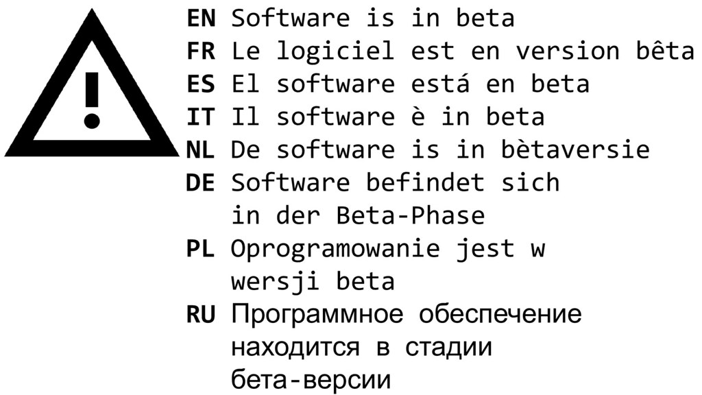 Although the software is still very beta and there is much more to be written. At the time of the presentation, the ZigBee radio support was still evolving. The radio could receive and transmit packets, the ZigBee network coordinator will allow the device to join and provision it with a network key, this key can be used to decrypt, encrypt and authenticate messages with AES-CCM*, some of the ZigBee Cluster Library (ZCL) commands are mapped, such as the Brightness Level set command.
But there is still lots to do! Please help out if you're interested in a pure Python ZigBee device library, if you want to improve your devices, or if you are just curious about what happens if you start poking at these sorts of devices.
Software components
 There are three main components involved:
github.com/osresearch/micropython/tree/efm32/ports/efm32- EFM32 port of MicroPython, with drivers for the Radio module and AES engine, and a pure Python SPI flash interface that can emulate a filesystem for OTA updates.github.com/osresearch/zbpy- ZbPy, a MicroPython IEEE802.15.4 and ZigBee stack with support for joining the network, decrypting packets, unpacking the various layers, and encrypting/integrity protecting messages.github.com/osresearch/arduino-cmsis-dap- firmware for a Teensy that can act as both an OpenOCD SWD probe as well as the serial console. If you already have an SWD setup (like the BlackMagic probes) then you don't need this part.
Hopefully the EFM32 port will move into the mainline MicroPython tree once it stabilizes a bit more. The ZbPy stack is very rudimentary right now and is where most of the further development needs to happen. Ideally we can set it up so that the Gecko board acts as a serial data to Zigbee NIC and we can develop the "firmware" on a real computer, then flash it onto the device once it has sufficient features.
Devices
2-button remote
 Ikea 704.085.95:
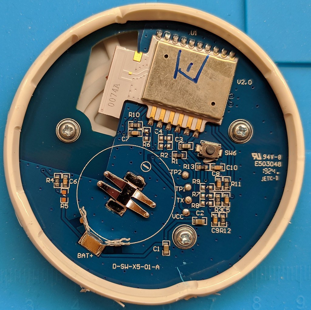
Easy to open. Test points are accessible through the case (but not the console pins). Definitely the best getting started platform for battery powered projects. Does not use the standard Gecko board, but the same CPU and Ikea maintained the same pinout for things like the SPI flash.
Ikea 704.085.95:
Easy to open. Test points are accessible through the case (but not the console pins). Definitely the best getting started platform for battery powered projects. Does not use the standard Gecko board, but the same CPU and Ikea maintained the same pinout for things like the SPI flash.
 Thanks for labeling the JTAG and console, Ikea. It really is a testatment to the DIY spirit of the company that they've made it this easy to experiment with the devices.
10W LED dimmer
 Ikea 503.561.87: Easy to open, 4 pin SWD port is ready for headers. Console needs soldering, but otherwise the best for getting started with AC powered projects.
 Uses the Gecko board and most of the pins have been mapped.
5-button remote
 Ikea 304-431-24 (E1524): Difficult to open, requires soldering headers. Otherwise a nice battery powered development platform. Five buttons on the front, one on the back and one red LED on a PWM capable pin.
2020 5-button remote
 E1810, sealed version of the remote introduced in 2020. Has a blue PCB and a matte finish. Much harder to open. Has the Draco 1.0 board similar to the Symphonik. Test pins are different, not yet probed.
Motion sensor
 Ikea 704.299.13: Easy to open and has a standard Gecko board. Haven't checked test points/etc yet.
FLOALT LED panel
 Ikea 404.363.16: Easy to open and has a standard Gecko board, didn't see any test points so requires soldering headers to the SWD port and console. This one is really nice once it is dim enough, although some stripes appear at very low brightness levels and it seems to occasionally strobe.
Symofonisk remote
 Ikea 603.704.80: uses a "Draco" board with similar pinout to the "Poly4B". There is a quadrature encoder with a built in switch that allows it to turn continuously. The pin outs haven't been mapped yet. There are four test pads accessible through the case - uart TX, RX, VCC and ground. SWD requires removing the back panel.
Gateway
 Ikea 403.378.06: Totally different architecture. There is a ten pin ARM debug port, but haven't experimented with it yet.
Ikea Tradfri firmware hacking

Resources
 |
 |
- Ikea release notes: https://ww8.ikea.com/ikeahomesmart/releasenotes/releasenotes.html
- Firmware update JSON feed: http://fw.ota.homesmart.ikea.net/feed/version_info.json
- Firmware images start at offset 0x1f6 and are loaded at 0x4000
- Silcon Labs EFR32 "Wireless Gecko": https://www.silabs.com/products/wireless/technology
- Tear down with schematic: https://diystuff.nl/tradfri/tradfri-zigbee-light-link-module/
- JTAG and firmware details: https://github.com/basilfx/TRADFRI-Hacking
- Other project to replace FLOALT firmware: https://github.com/zw/TRADFRI-Hacking/tree/master/hacks/L1527
- Basestation security: https://mjg59.dreamwidth.org/47803.html
- Nordic OTA file format has same 0x0BEEF1LE header: https://github.com/NordicSemiconductor/pc-nrfutil/blob/master/nordicsemi/zigbee/ota_file.py
- Zigbee spec for OTA format (page 9) http://www.zigbee.org/wp-content/uploads/2014/11/docs-09-5264-23-00zi-zigbee-ota-upgrade-cluster-specification.pdf
- OTA struct: https://infocenter.nordicsemi.com/index.jsp?topic=%2Fcom.nordic.infocenter.thread_zigbee.v3.0.0%2Fstructzb__zcl__ota__upgrade__file__header__s.html
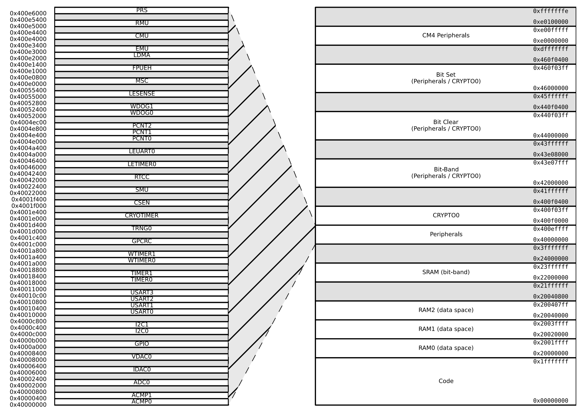
Memory layout for the board, helpful as new devices are being mapped into the MicroPython environment.
Brightness adjustment
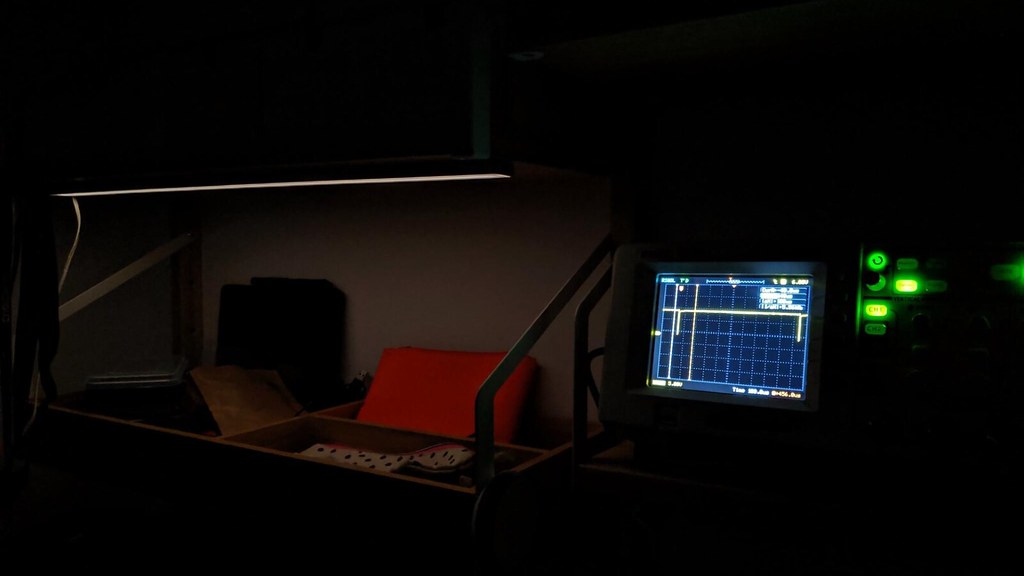
 Lowest default firmware dim is 50usec with a 1kHz period is way too bright. Like eye-blinding at night. The ERF32 runs PWM on timer1 to do low side switching on the +24V output.
 Modified firmware with a 1usec PWM produces a much more acceptable nightlight. Demo video showing how much dimmer the updated firmware is able to produce. This also works on FLOALT panels, although at the lowest dim the light is very non-uniform due to LED spacing.
 Replacement brightness curve compared to the default one in the firmware. The stock firmware has 0x380 as the lowest value and uses floating point to generate the curve; due to space constraints the replacement one is piecewise linear, but still produces a similar ramp effect. The code is currently really hacky and requires hard-coded function offsets; a better system needs to be put together to make this usable for non-hardware hacking users.
static inline void
thumb_thunk(
        const unsigned addr
)
{
        // force thumb addressing by setting the bottom bit of the address if it is not already set
        void (*func)(void) = (void*)(addr | 1);
        func();
}

void
brightness_table_fill(void)
{
        volatile unsigned * const brightness_table = (void*) 0x20005f74;
        if (brightness_table[0x100](0x100) != 0)
            return;
        brightness_table[0x100](0x100) = 1;

        thumb_thunk(0x099fc);
        thumb_thunk(0x0a7f6);
        thumb_thunk(0x176a2);

        // piecewise linear ramp for now, approximating an acceleration
        unsigned pwm = 0x20;
        unsigned bright = 1;
        unsigned acc = 8;
        brightness_table[0](0) = 0;

        for(unsigned i = 0 ; i < 8 ; i++)
        {
            for(unsigned j = 0 ; j < 0x20 && bright <= 0xFF ; j++)
            {
                brightness_table[bright++](bright++) = pwm;
                pwm += acc;
            }

            acc += acc;
        }

        thumb_thunk(0x098b0);
}