FT 817
Yaesu FT-817nd
 In addition to the IC-7000 that we use at NYCR for our base station radio, I also use a Yaesu FT-817nd portable rig.
Serial port
 If you don't want to spend a lot of money on the official USB serial adapter, you can make one with a few short pieces of wire and the FTDI adapter you have already. The pinout for the three serial pins in the ACC connector is as shown in the above image -- FTDI black to ground, Yellow to Radio TX, and Orange to Radio RX.
The default baud rate in CAT mode is 4800 (set via menu #14 CAT RATE), in CLONE mode it is 9600. CHIRP can talk to the radio and ka70ei has documented the serial protocol.
My tools to talk to the radio are github.com/osresearch/ft817.
Menus
Important menu items:
- 42: Repeater shift frequency
- 48: Tone frequency
Hidden menu is accessed by powering up the radio while holding down A, B and C.
Reset all settings by powering up the radio while holding down F.
Sending 00 00 00 00 ba reports 00. Sending ff ff ff ff ba causes the radio to turn off. And appears to have broken something in the battery configuration. The screen reads 17.9 volts when powered by the external DC adapter.
Reverse engineering
 CPU is a HD64F2345FA20V, which is in the H8S/2300 family from Renesas (formerly Hitachi). This appears to be the flash ROM version and it is supported by IDApro, which means that reverse engineering the firmware and flashing new code might be possible.
The datasheet (giant PDF) does say on page 555 that "the flash memory can be reprogrammed up to 100 times", which is not a very high number. Too much hacking could be bad; it might be worth investigating that flash overlay, which allows "Part of the RAM area can be overlapped onto flash memory, to emulate flash memory updates in real time".
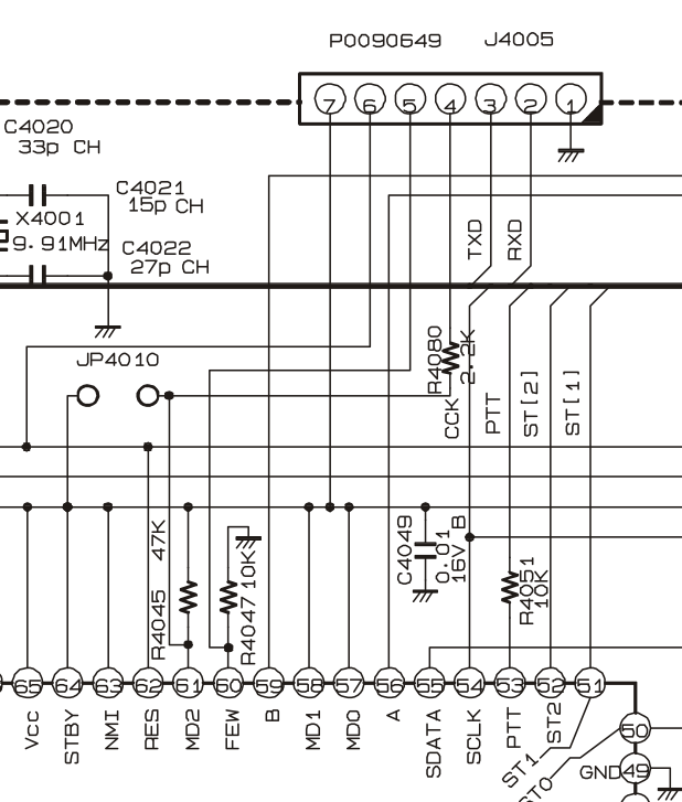 User program / Boot program mode both use the serial port, which is exposed on the seven pin header J4005. Selecting the mode at reset is configured with pins FWE, MD0, MD1 and MD2. MD0 and MD1 are wired high. MD2 has a pullup, FWE a pulldown, and both are connected to the same header. Looks like that one port can be used to initiate programming and to talk to the device.
| FWE !! MD2 !! MD1 !! MD0 !! Mode |
| 1 |
| 1 |
In boot mode only entire-chip operations are supported. In user mode, if there is a user mode programmer, the individual blocks can be erased and rewritten. Also, boot mode appears to have a built-in full-chip erase and probably should not be used!
- Host transmits number of programming control program bytes (N), upper byte followed by lower byte
- H8S/2345 transmits received number of bytes to host as verify data (echo-back)
- Host transmits programming control program sequentially in byte units
- H8S/2345 transmits received programming control program to host as verify data (echo-back)
- Transfer received programming control program to on-chip RAM
- End of transmission
- Check flash memory data, and if data has already been written, erase all blocks
- After confirming that all flash memory data has been erased, H8S/2345 transmits one H'AA data byte to host
FT-350 firmware
The FTM-350 has a firmware updater and programming mode. It sends 00 at 19200 until it receives a reponse.
 winedbg
 //br 0x00402760
 br *0x402c0f -- right before the boot loader is sent

 stty -ixon < /dev/ttyUSBn

 Send: 00 00 aa aa
 Wait for: 55
 Send: aa a1
 Wait for: 06 60
 Send: 06 60
 Wait for data, echo each byte

 After 0x660 bytes, send AA
 reply 04 d8
 send 6
 reply 3f 01 80 // maybe the baud rate? -- 384 is 01 80
 try changing baud rate?  nope.  leave it at 19200
 send BF 24 // why?  it is in the code
 reply something
 send 6
 reply 6
 send 6
 reply lots of data