SolderTime Desk Clock
Solder:Time Desk Clock
 We had three workshops on building the Spinkenzie Labs Solder:Time Desk Clock at my office and made a timelapse of the construction process.
Kit notes

Soldering order
My suggested ordering of soldering:
- 100 Ohm resistor (brown, black, brown)
- Four 10K Ohm resistors (brown, black, orange)
- Eight 0.1uF capacitors
- Three diodes (be sure to check polarity)
- Crystal (be sure to not short pins)
- Five sockets (be sure to line up notch with U-shape on PCB)
- Voltage regulator (solder one pin to hold it in place and lay it flat against heat sink)
- Battery
- Buzzer
- Programming pins (12 normal headers, short side through the PCB. solder one pin then adjust for straightness)
- Two buttons and power jack -- done together they make a nice triangle to support the PCB
- Cut the Swiss pins into eight 7-pin segments and install on each of the LED modles.
- Install the LED modules on the side opposite the components-- be sure to note the orientation of the "bumps"
- Install the chips -- carefully bend the legs straight and pay attention to the U-shaped cutout on top of the chip.
- Smoke test it!
Debugging
- If you want to hack new hardware onto the board, do not assemble the acrylic case. It is a press fit and once assembled very difficult to get to the prototyping area.
- Be sure to sand or file the tabs on the case; otherwise it will break the acrylic when you force it.
- RTC not advancing or running very slow? You might have bridged the crystal legs. They are very close together.
- Part of the display flickers, flashes or doesn't appear? Check your solder joints on the 74138 chip for that region. Each handles 1 ⅓ of a display.
Hardware
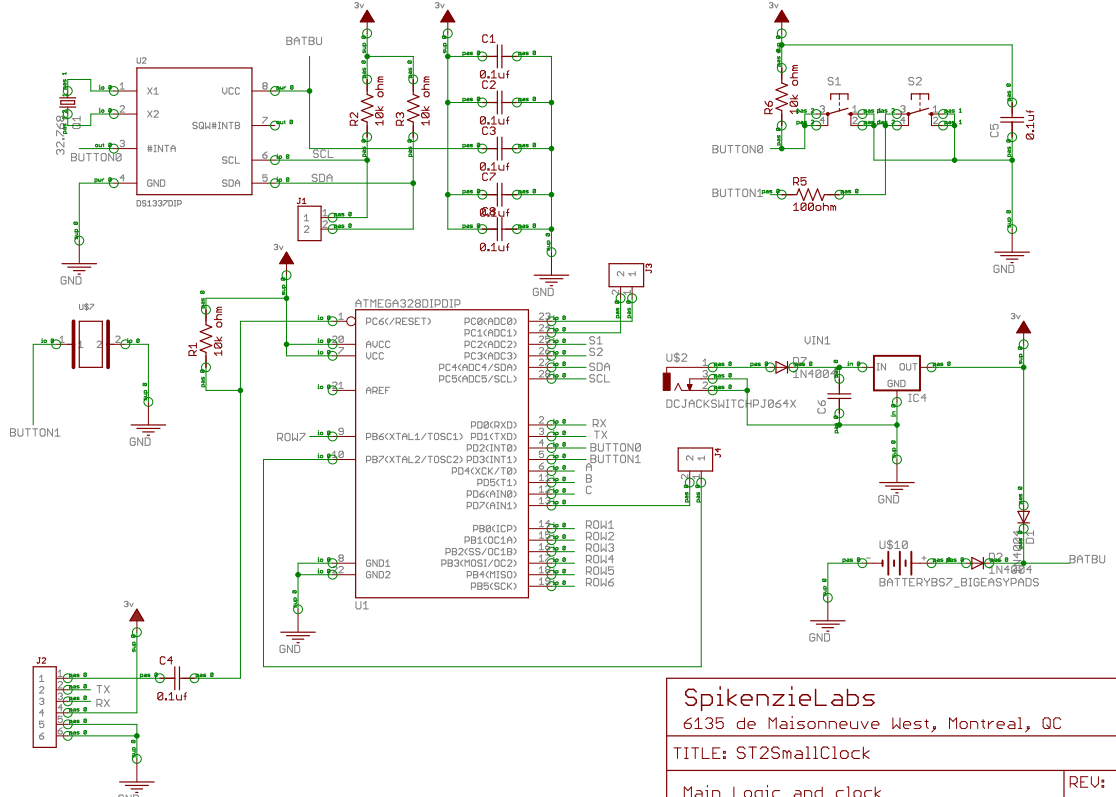
- Schematic
- Four 5x7 red LED panels, with normal column/row address lines.
- Three 74138 octal decoders connected to the columns (4 unused on the last decoder)
- PORTB0-6 directly source current to drives the 7 rows inputs
- PORTD5-7 selects the column
- PORTC2-3 selects the decoder (01, 10 and 00. 11 = all off)
- PIND2-3 are pulled low for the two buttons.
- Because the currently selected decoder sinks current from all the LEDs turned on in the current column, turning on a different number of LEDs causes varying brightness.
Programming
 |
 |
- Program as Arduino Dsomething with ATmega328P, programmer Arduino as ISP
- When compiled with Arduino 1.0.5, there is lots of flickering.
- Change the constant to
Timer1.initialize(100)toTimer1.initialize(50)inST2_Setup.ino - Or use my improved firmware.
- Change the constant to
Improved firmware
 My updated Arduino source files are github.com/osresearch/soldertime. The major changes:
-
Reworks the matrix code to use fewer magic numbers in the main loop. Hopefully easier to understand what is going on.
-
Removes (dead?) code in the startup and main loop. Perhaps left from debugging or other clock platforms.
- Converts the font to use an ascii art bitmap for each character so that it is easier to edit. Now rather than defining characters like "
127,9,25,41,70, // R", thefont.cfile has:
        {  // R
            _XXXXXXX,
            ____X__X,
            ___XX__X,
            __X_X__X,
            _X___XX_,
        },
- Converts from a 1-bit monochrome to 8-bit grayscale and adds per-pixel PWM support. Pulsing dots and dimming are now possible.